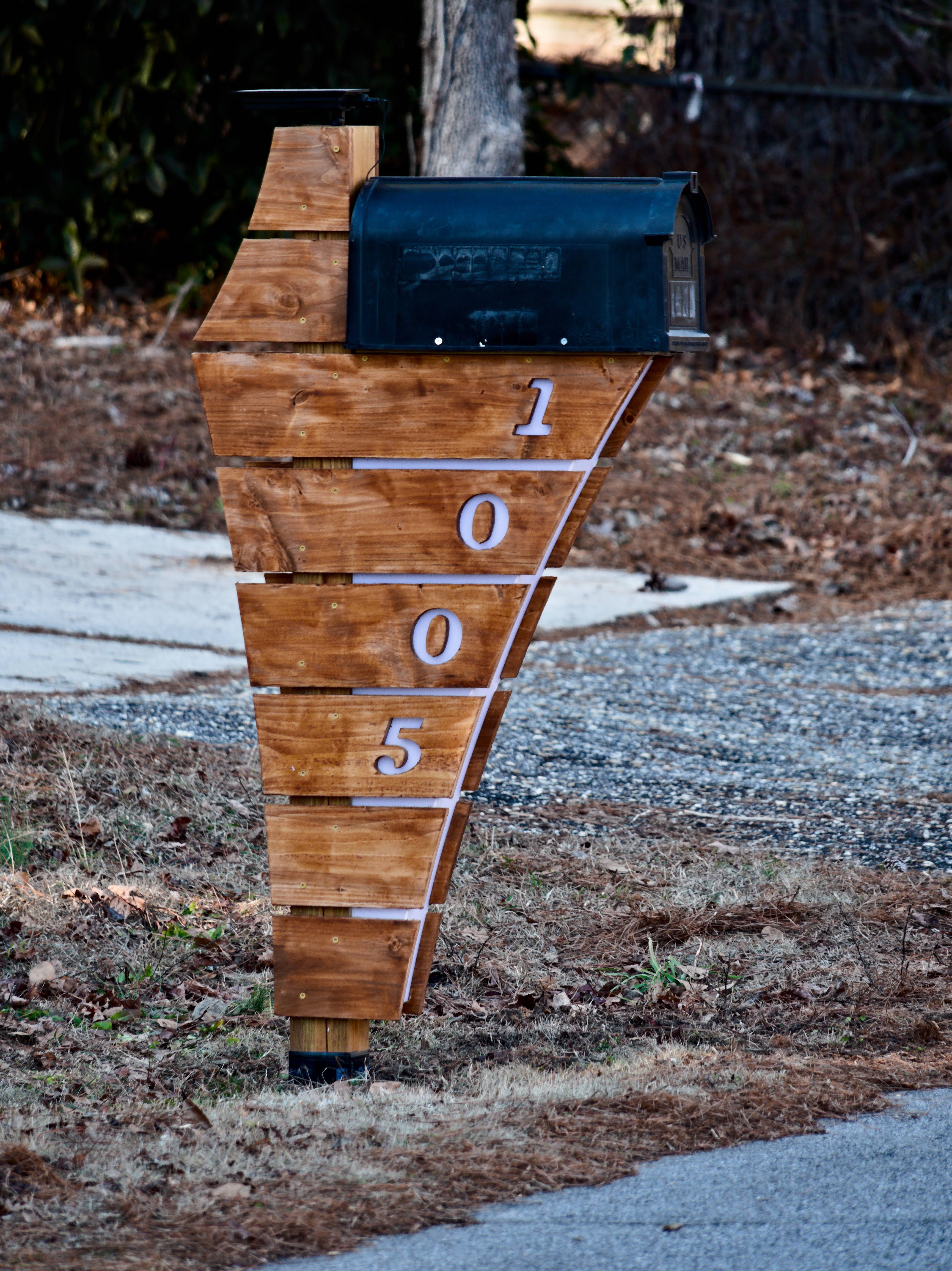
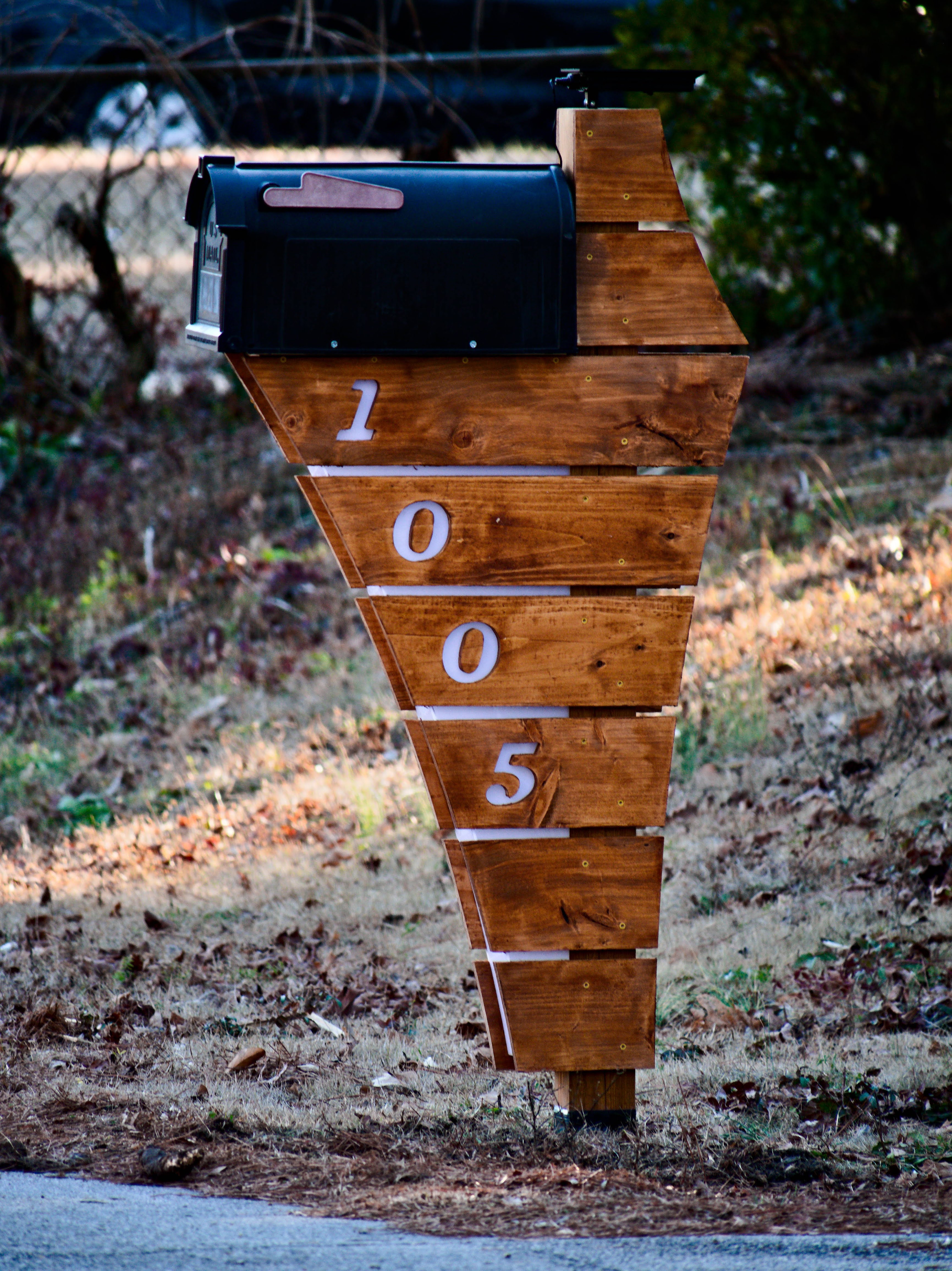
This is a replacement for our aging mailbox. I wanted to do a somewhat mid-century design since the house and rest of the neighborhood was built in that time. I also wanted to make the numbers visible at night if possible.
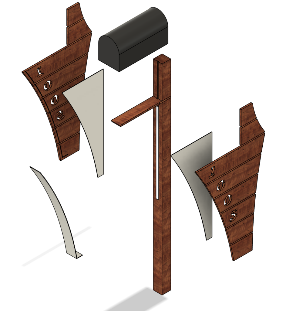
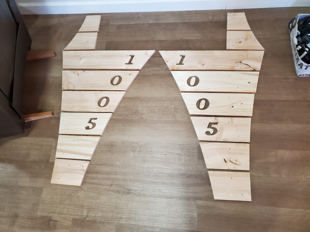
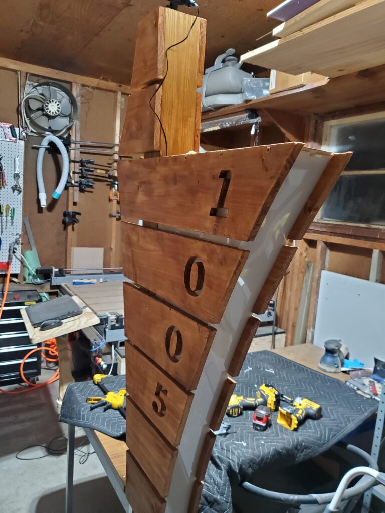
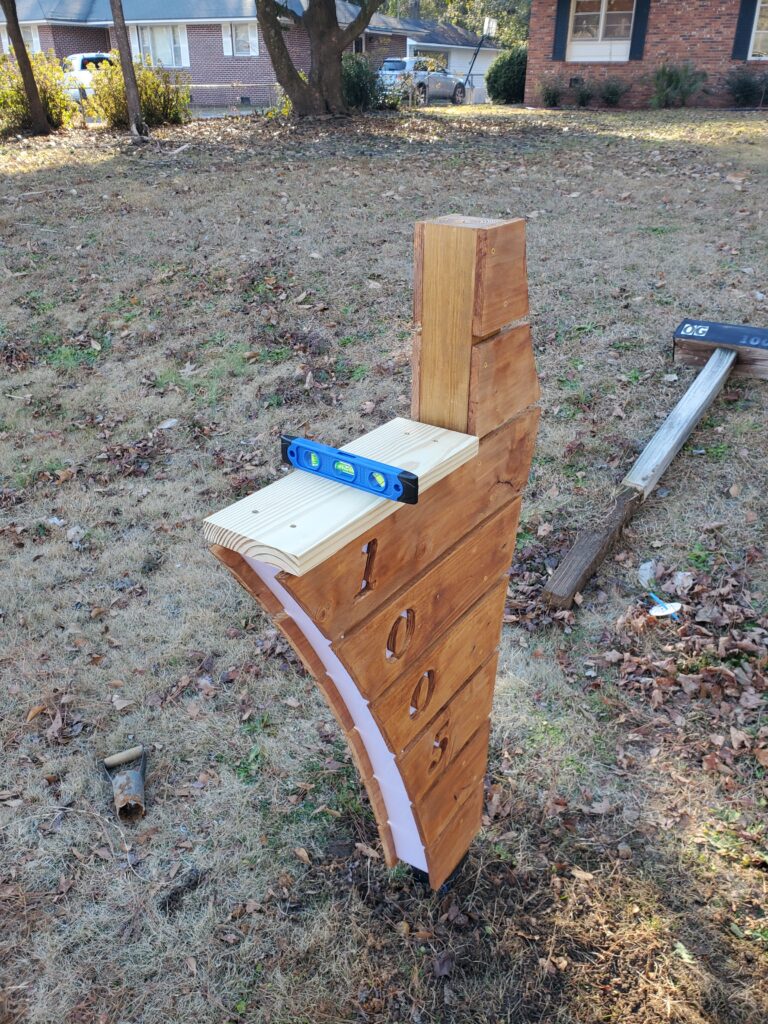
After playing around with some different designs and lighting ideas, I settled on this design where several cedar boards make up the sweeping profile, and the house numbers are directly carved into those boards so that they can be backlit by an LED strip. Everything is mounted to a 4×4 post which is set 24in deep and with a little bit of concrete. Translucent white acrylic acts as a diffuser so that it appears the numbers and front of the mailbox itself are glowing.
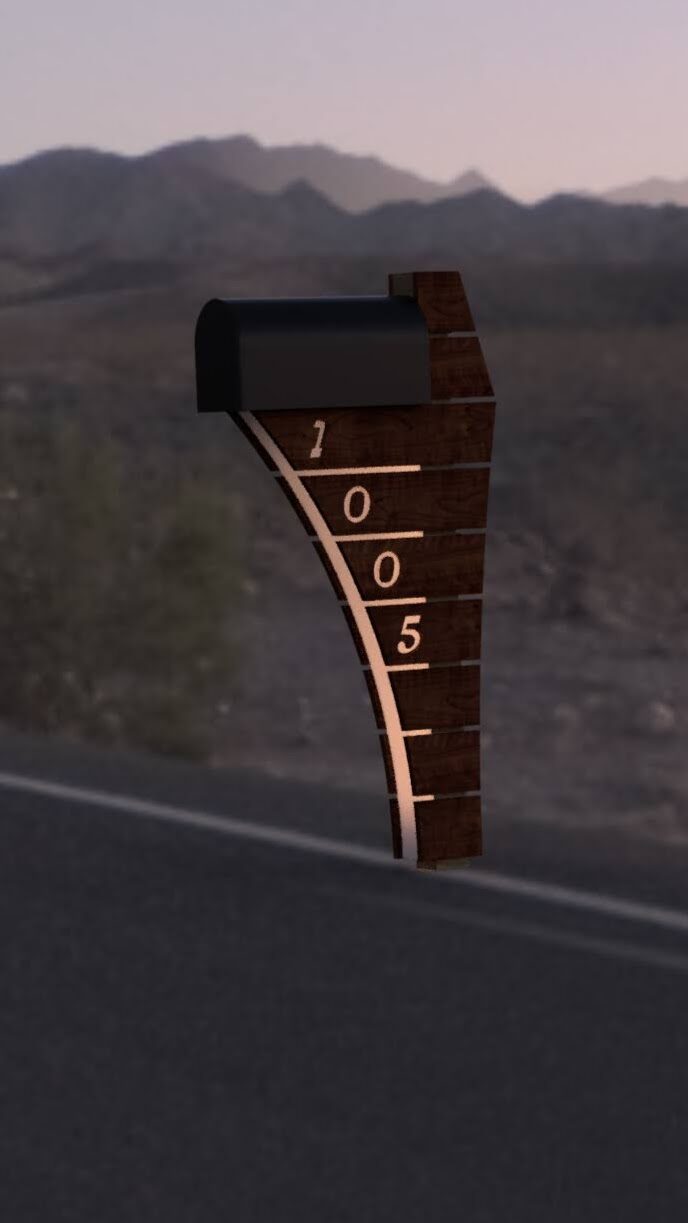
The lighting is provided by a 1m long 24v COB LED strip connected to a small solar panel battery. These were purchased off the shelf.
Fusion render of mailbox with lighting
Exploded view of mailbox components
Side panels cut on CNC router
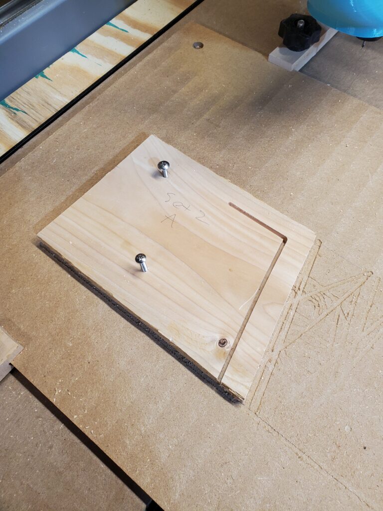
Slot on back of cedar panel which accepts acrylic diffuser
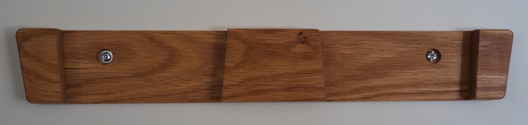
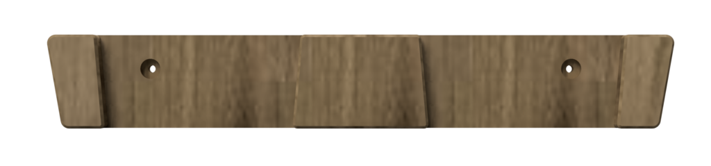
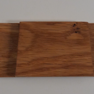
Over the past couple years, I have made several sets of downhill skis. To display and store them, I wanted a way to hang them on a wall with the topsheets visible. The design I came up with is a simple piece of hardwood milled to shape with a CNC router. It has an angled design for aesthetics, and two pockets which taper from top to bottom. This taper allows the ski to wedge into the hanger at a point where the width of the ski is increasing toward the tip, and corresponding to the width of the machined pocket.
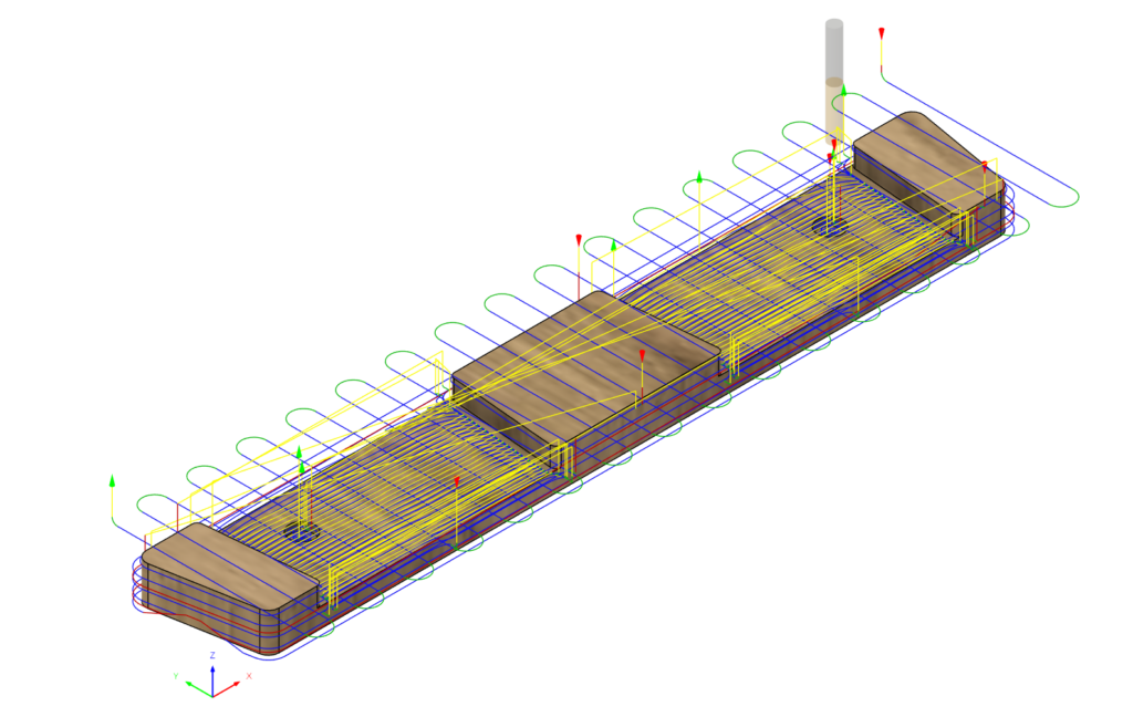
The actual machining process for this part is quite simple, with just one setup and no need to flip the part. It can even be accomplished with a single tool by skipping the chamfer operation.
The hangers are mounted to the wall with 2 screws in drywall anchors.
If you would like to make one yourself, get the download below for the Fusion file. This includes the parametric 3D model, as well as the programmed toolpaths and CNC setup.
Digital Download – CNC Wood Ski Hanger Fusion File
This is a digital download of a Fusion design file (.f3d) which contains:
3D Parametric CAD Model
CAM Setup, Including Stock
CAM Toolpaths
$5.99Original price was: $5.99.$1.99Current price is: $1.99.
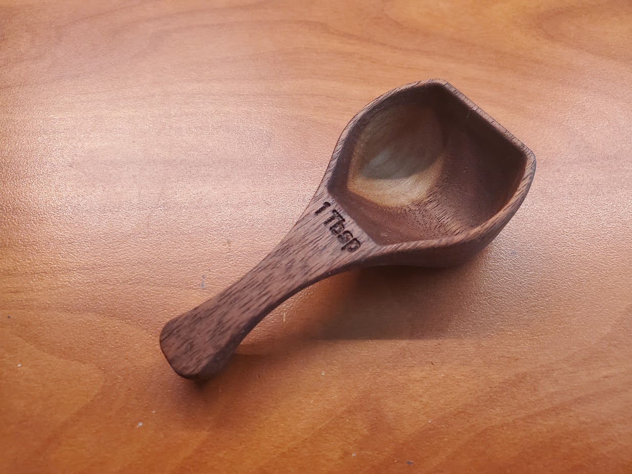
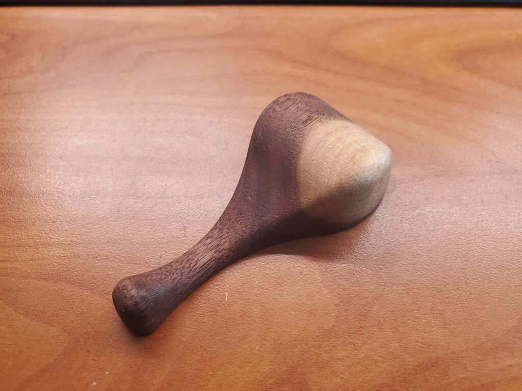
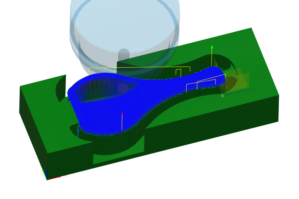
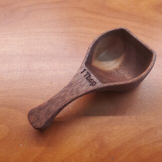
This little spoon was a quick design I did as a demonstration of the capabilities of the CNC router at Lansing Makers Network, where I was a member at the time. It was intended to be a relatively quick demonstration of 3D, 2-sided carving which I could repeat several times throughout an event we were hosting. Each one took around half an hour. I think I ultimately made 5 spoons and sold 2 at the event as a fundraiser, then gave away the rest at a later date.
If you want to make your own, I’ve made the Fusion design and CAM setups available for free download in my store. Here is the link.
CAD
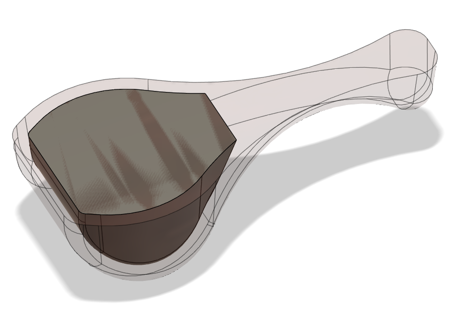
The design itself was a fairly simple one in Fusion. It is extruded from one sketch, then cut by another sketch drawn from the side. The most difficult part was then modeling the recessed portion of the scoop. I started with an offset surface, then turned that into a body that represented the negative space. I could see the properties of the body to confirm that it was close to the volume (1tbsp) that I was trying to acheive, then use a combine feature to subtract it from the main body.
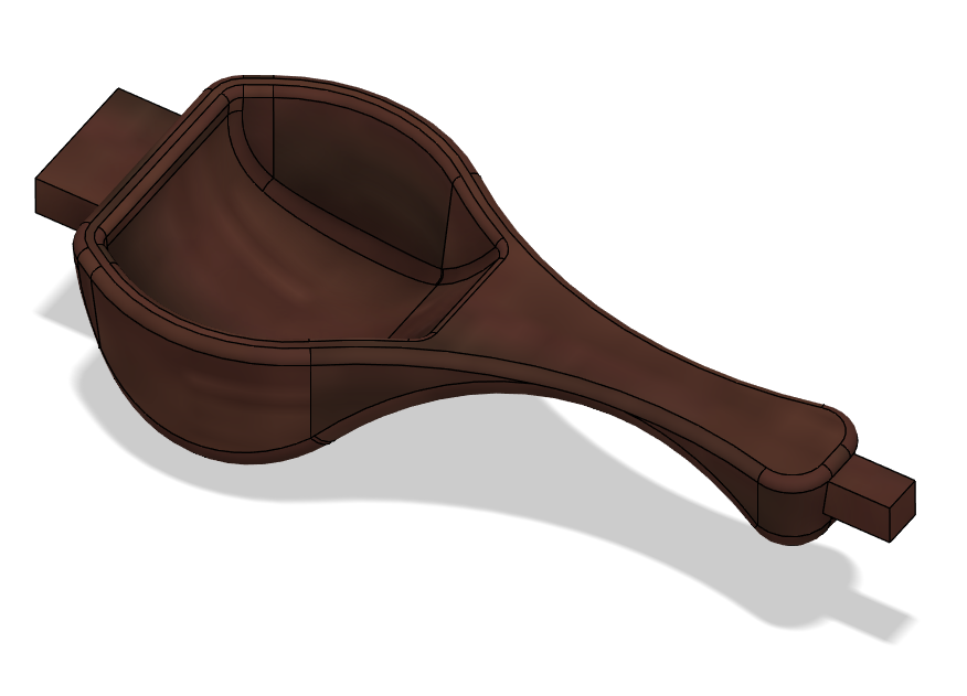
I also modeled some tabs which will hold the spoon in place during the machining operations.
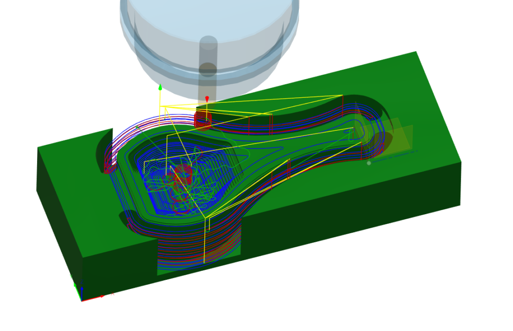
CAM
My strategy for machining these was to use a temporary MDF jig to position and hold the stock material. I bored holes in each stock blank, then a matching set in the piece of MDF. This allowed me to quickly clamp down each piece in the same place, and to easily flip the stock for 2-sided machining. The order of operations was:
Roughing
3D Pocket toolpath
1/4in 2F up-cut carbide end mill
18000rpm 150in/min
0.01in stock to leave
Machining boundary set to limit cutting area
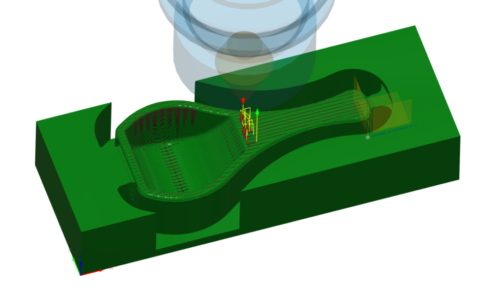
Finishing
3D Parallel toolpath
R1/32in 5deg Tapered Ball Nose
18000rpm 40in/min
0.009in stepover
Engraving
Engrave toolpath
45deg V-bit
18000rpm 40in/min
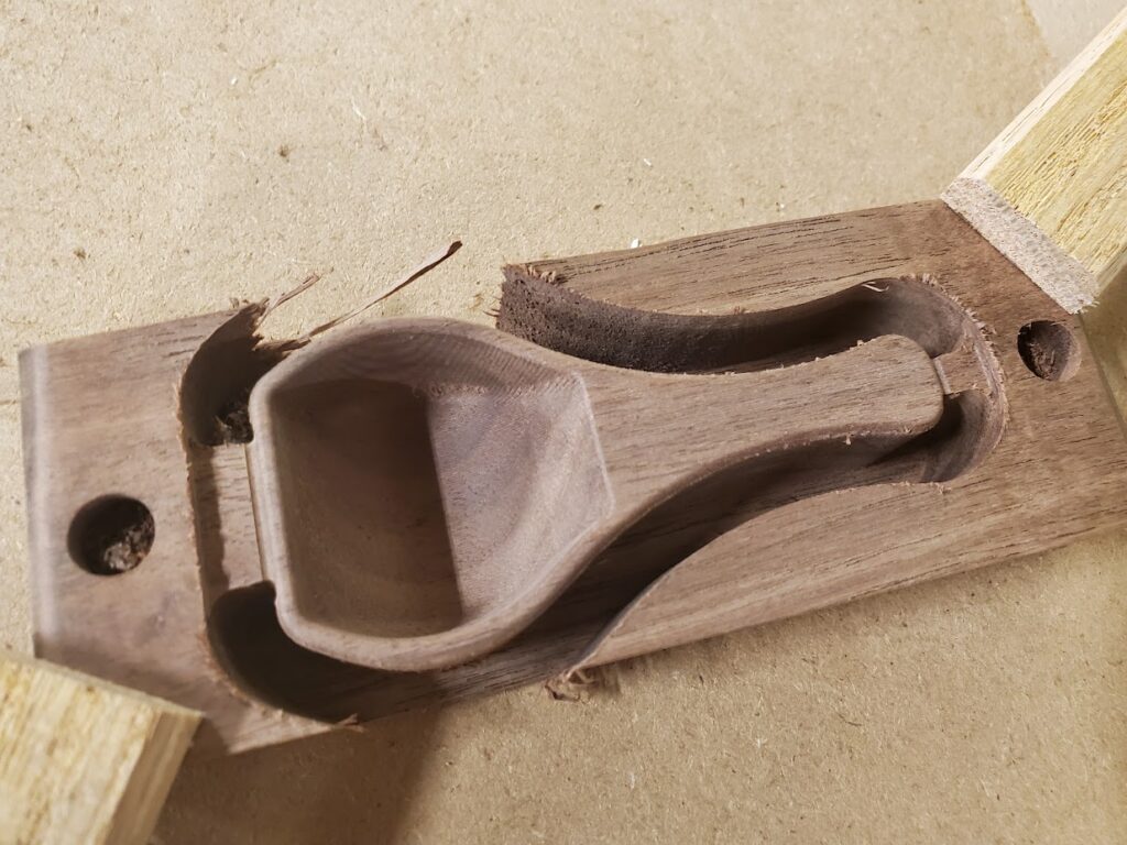
Once the first side is complete, the stock is removed, flipped, and placed back on the same dowels. The CAM setup for the second side was almost the same, without the engrave toolpath. Then it was a matter of cutting off the remaining stock and sanding down the tabs. I did a quick hand sanding and oiled with a food safe mineral oil.
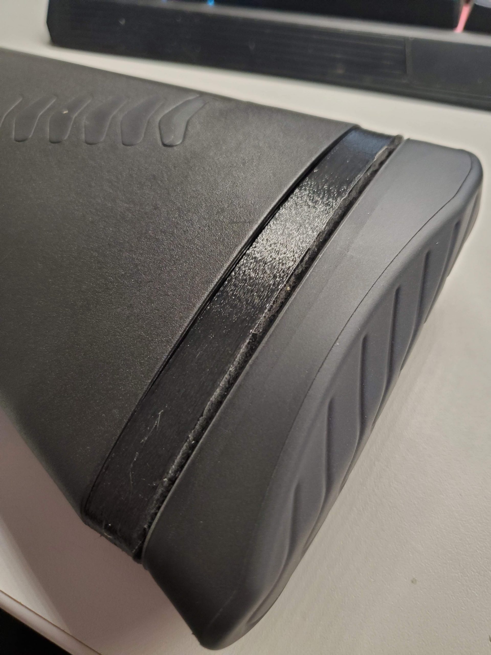
“Length of pull” is the distance from the buttstock to the trigger on a long gun. For shotgun shooting, it is an important part of the ergonomics and, therefore, accuracy of the gun.
A friend of mine reached out about coming up with a way to add length to the stock of a Benelli shotgun without modifying the gun itself. There are commercial solutions, like a rubber sock which slips over the stock and extends the length, but that is far from an elegant solution. You can also buy replacement butt pads in varying lengths for $60-$100 each.
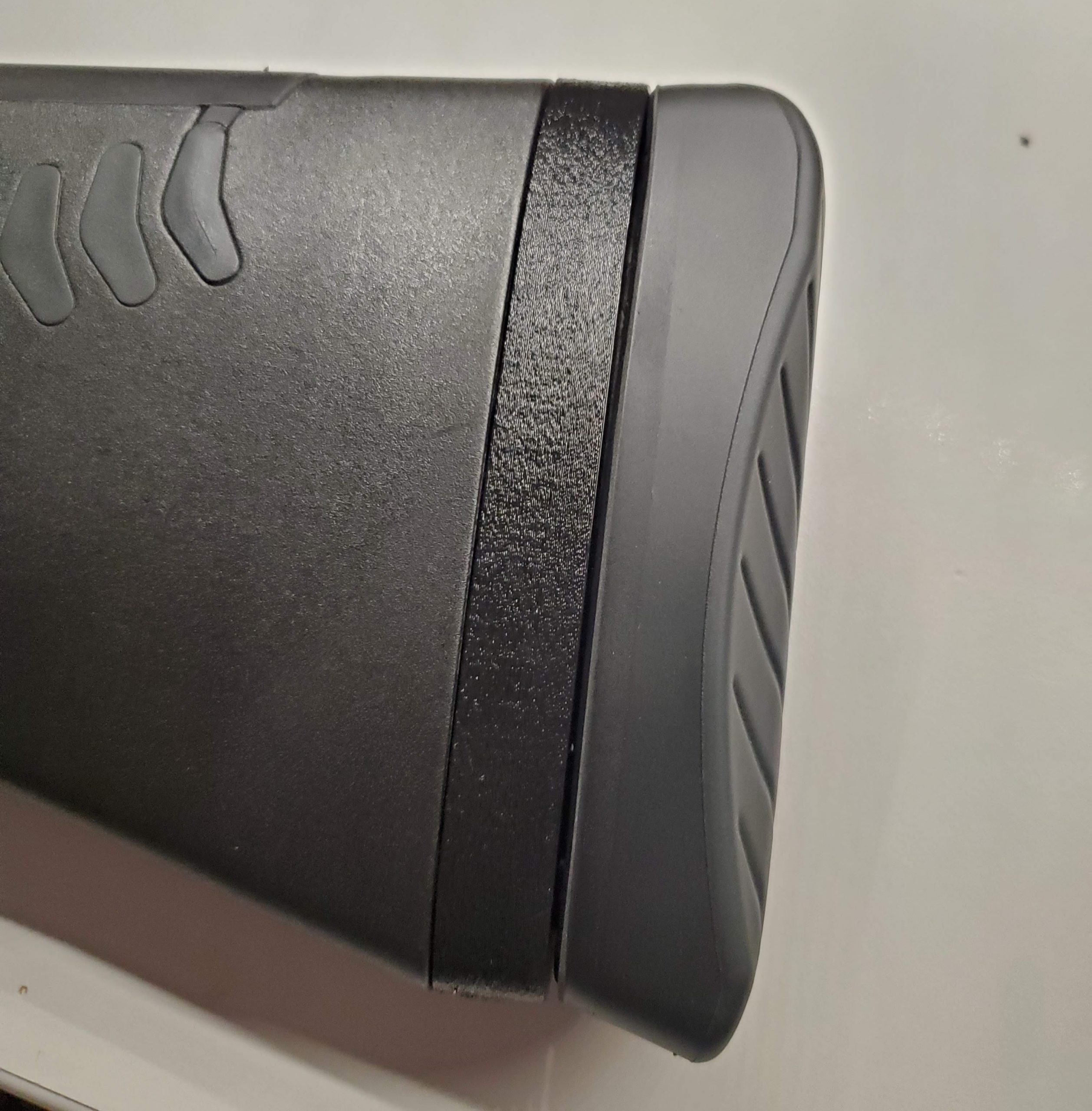
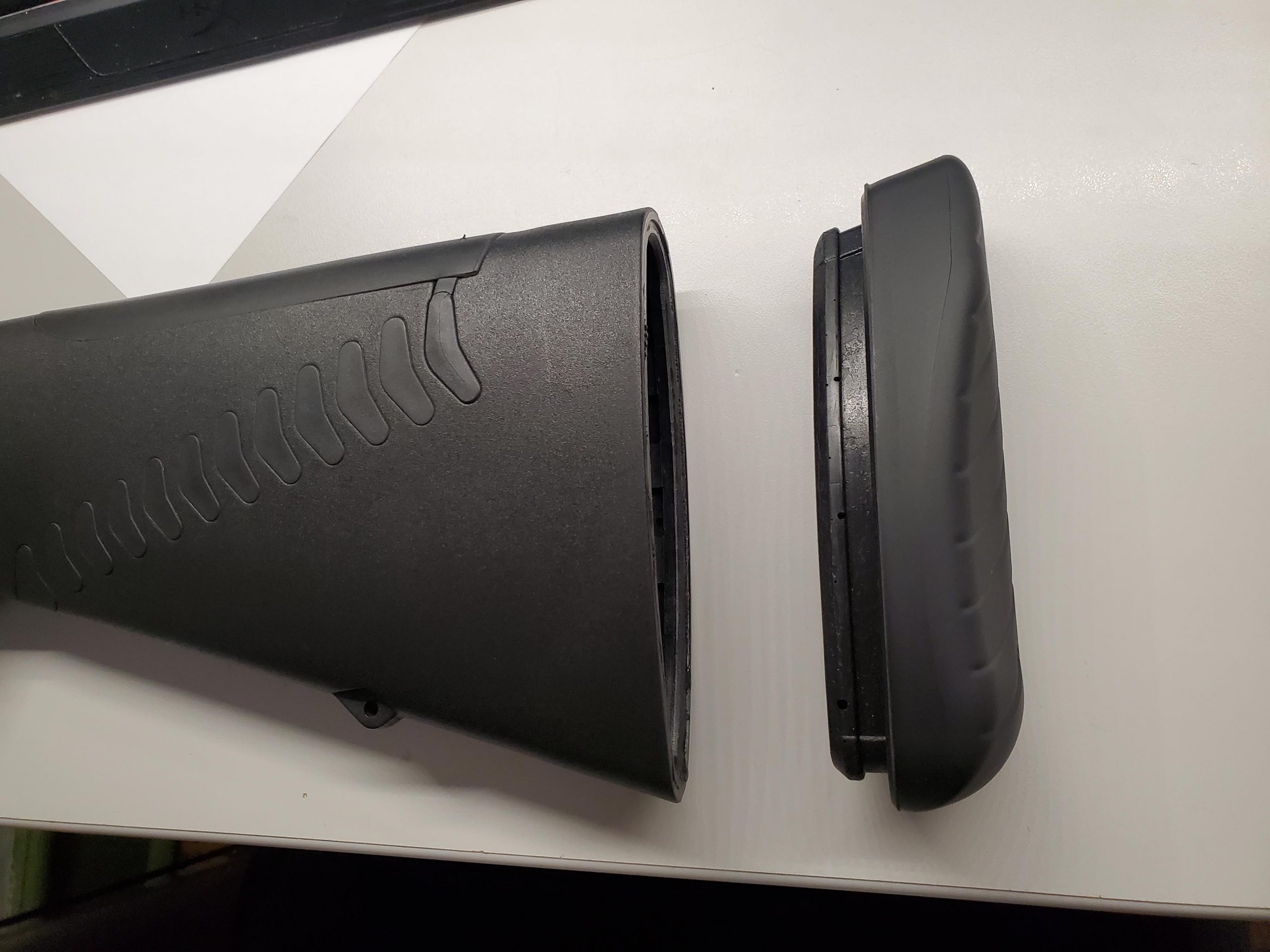
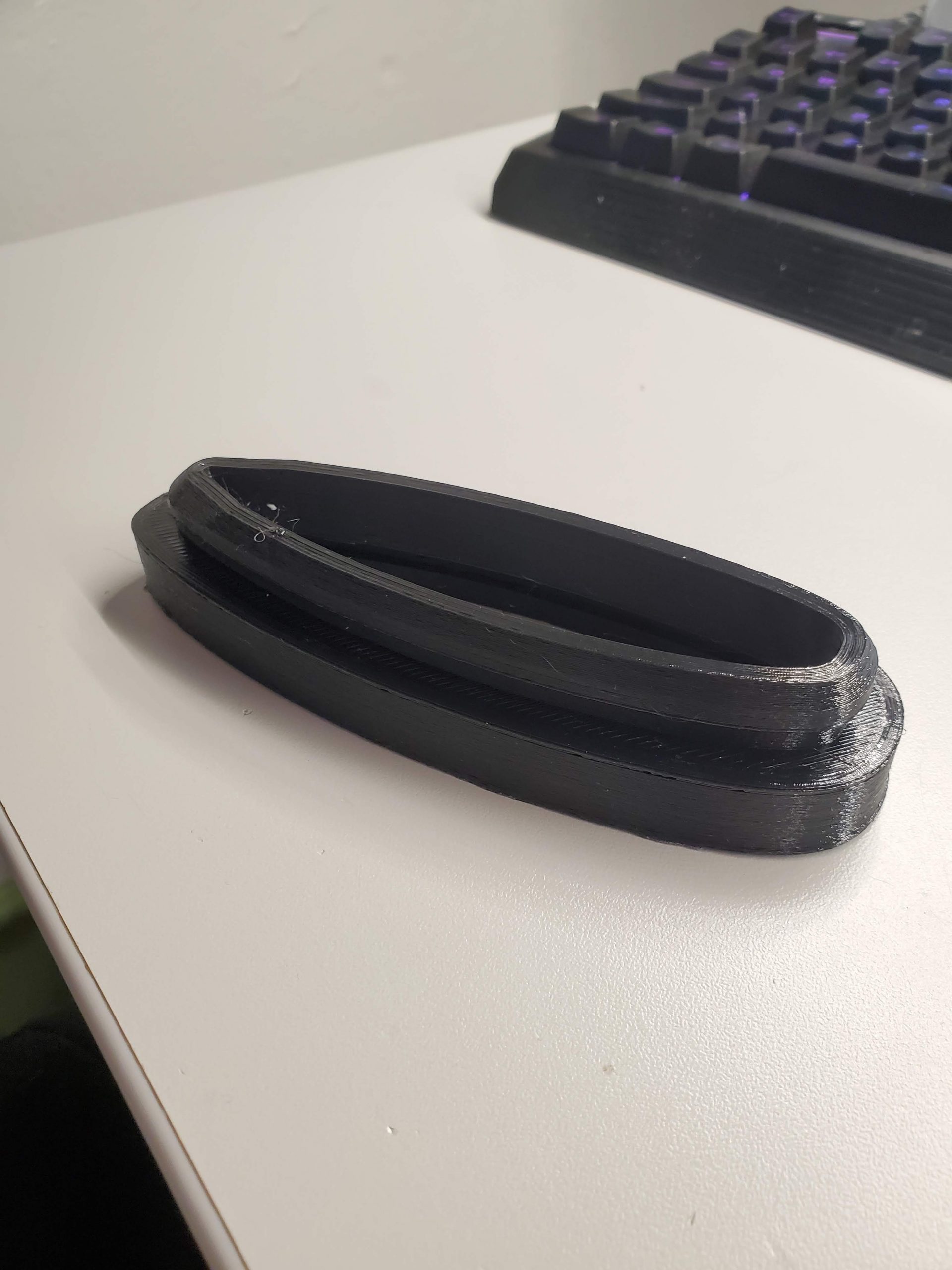
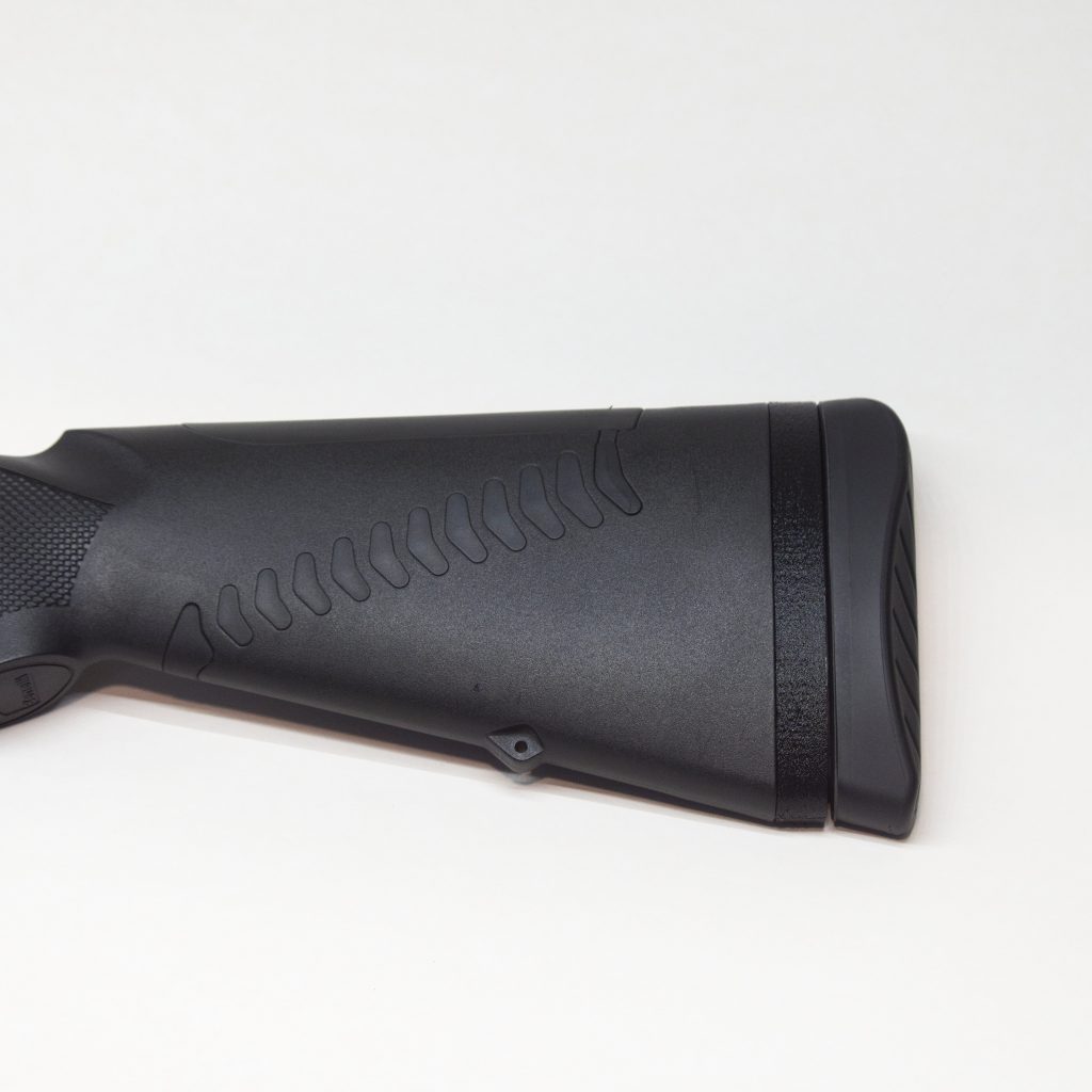
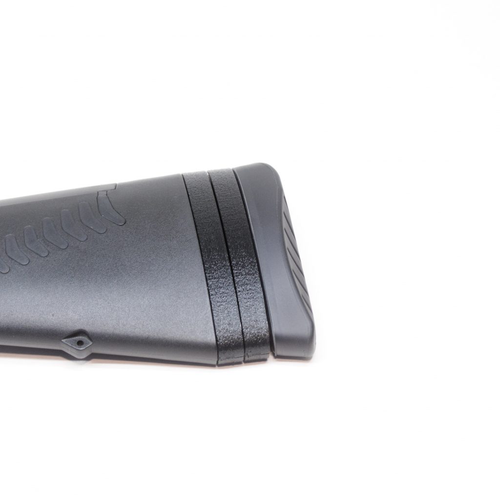
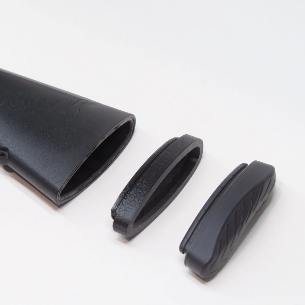
The Benelli design consists of a male-female interface. The male side is on the butt pad which is a two-shot injection molded rubber part with a soft gel pad molded onto a firmer rubber flange. The female side is just a recessed lip molded into the hard plastic of the butt stock.
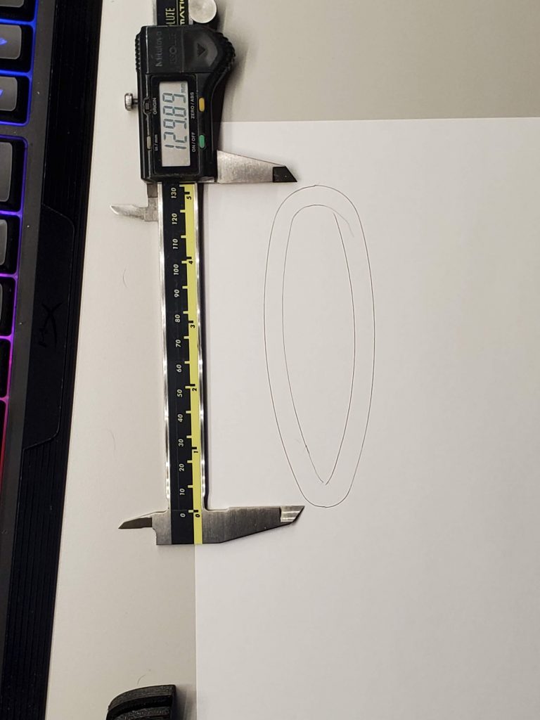
So the reverse engineered part will just need to match the profile of the stock, and then replicate that mating interface on both sides and fill in some space between the two. The first step is matching the profile, which is accomplished by tracing the outline, importing the image into a CAD program, and manually fitting a spline.
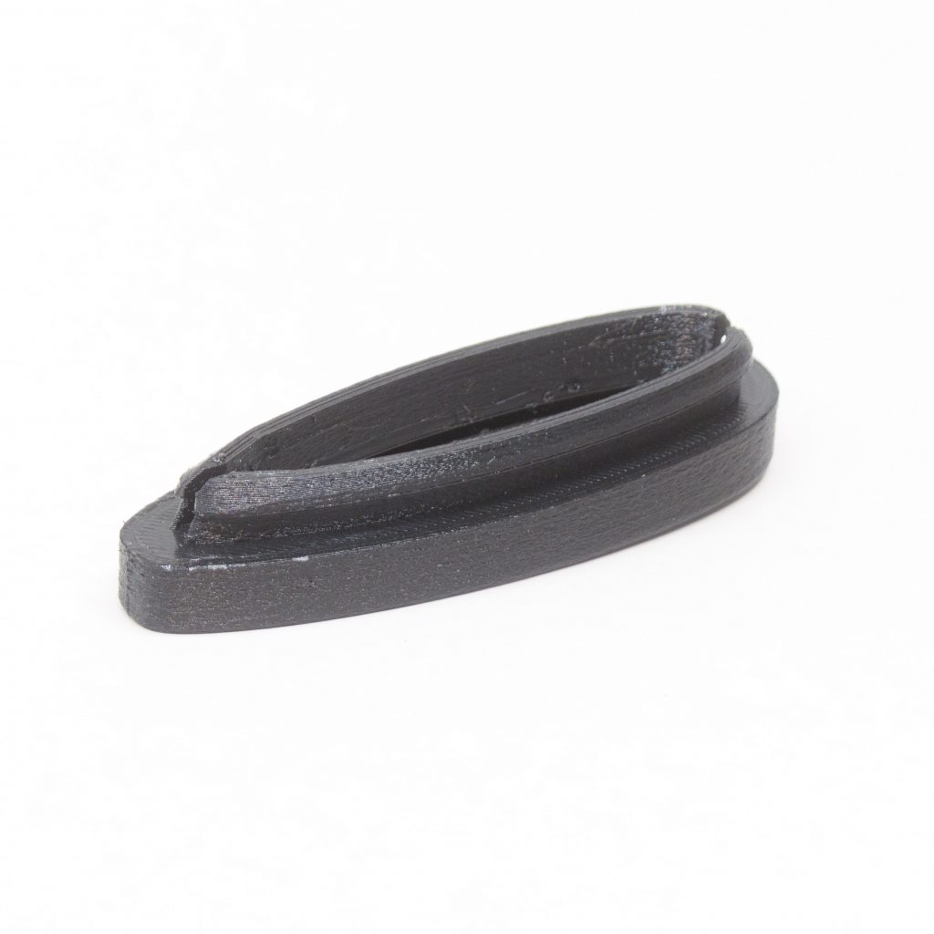
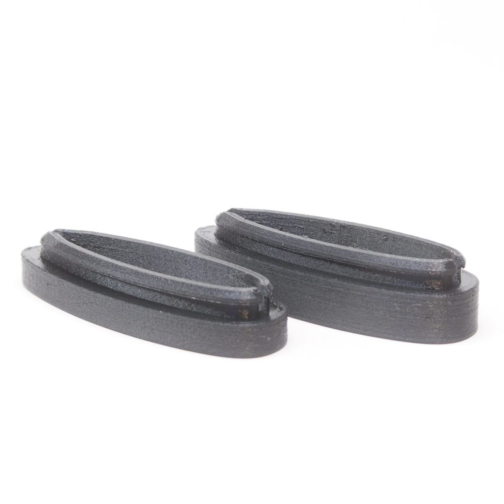
The rest was accomplished with manual measurement and trial and error with some assumptions about how the fit will work. I included some tolerance on the overall size and particularly the depth of the receiving side. I wanted to maintain the ability to stack multiple spacers on top of each other.
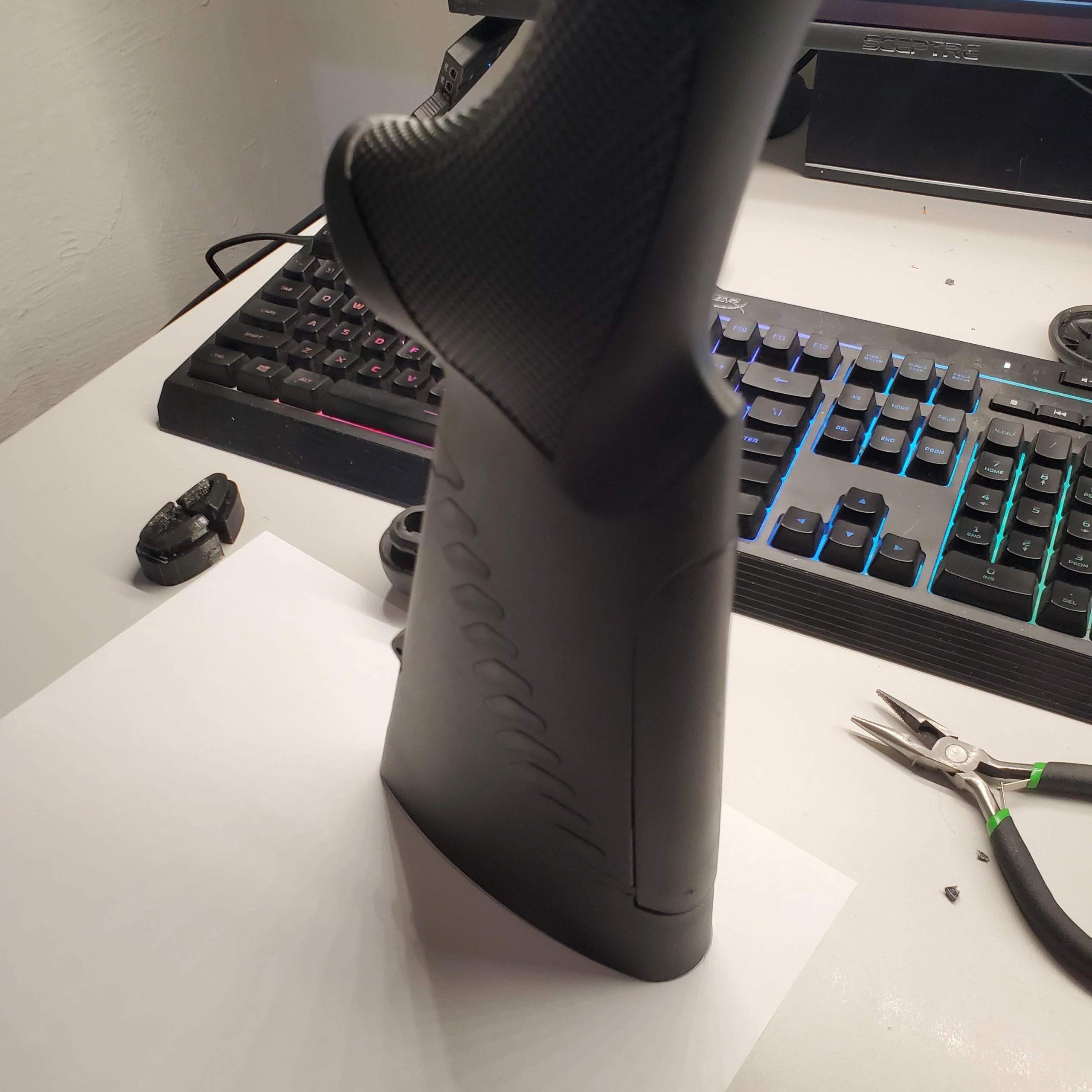
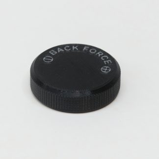
Side Note: the check pattern on the side of the Benelli stock is a functional design feature. The hard plastic is cut away in a pattern such that the center of each “check” is a hinge point in a compliant mechanism. This allows the stock to have some flexibility in the longitudinal axis to absorb recoil. The holes are plugged with a soft rubber which provides dampening.
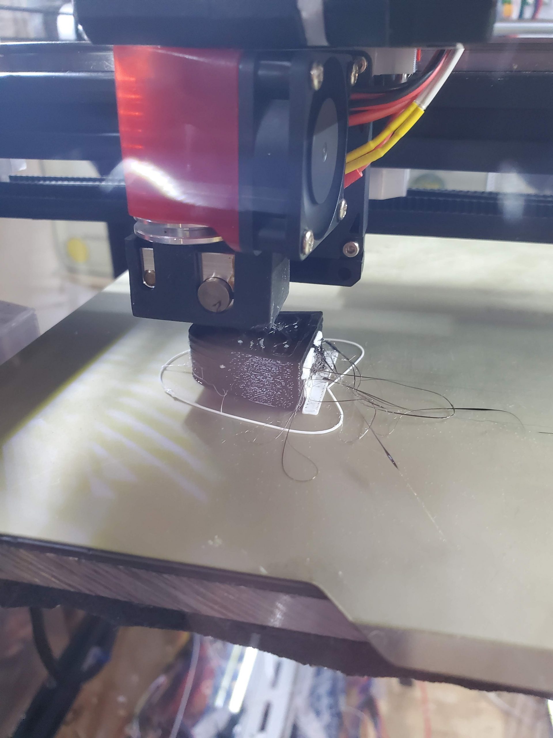
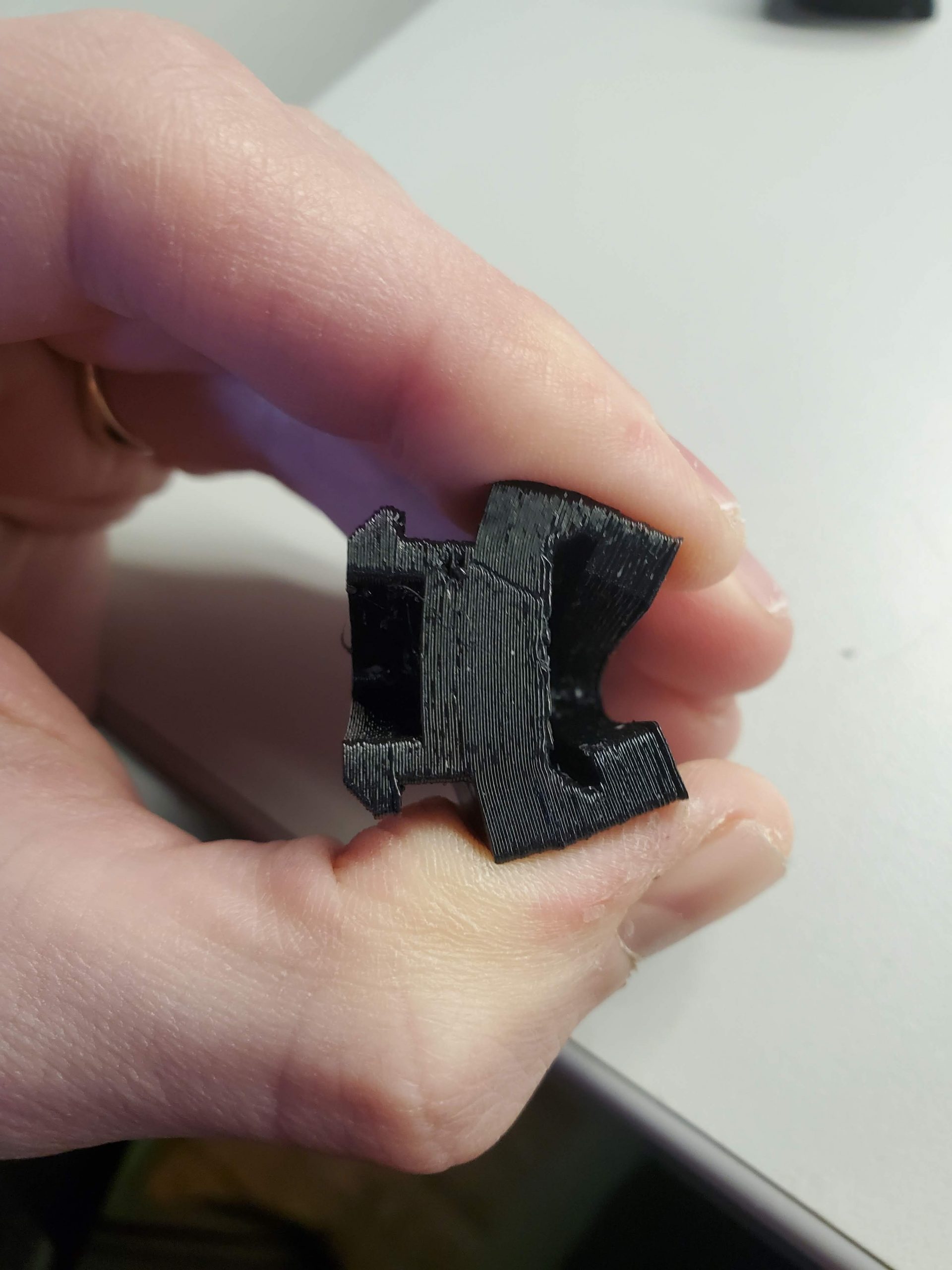
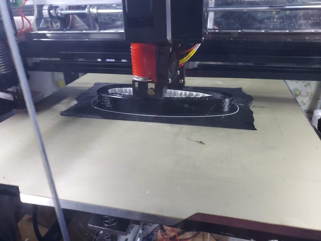
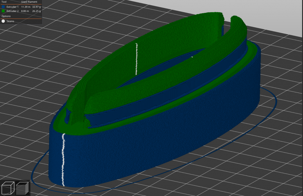
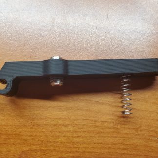
I decided print the part in flexible TPU, which I had never used before, so I did some small test prints. First with TPU support material, but that proved very difficult to remove from the part, so I used the second printhead on my IDEX (independant dual extrusion) printer to print the support in PLA instead, which pulls right off of the TPU cleanly.
Satisfied with the process and machine settings for the print, I loaded and printed the first prototype. This initial part did work, but I wasn’t satisfied with the fit and the material was more flexible than I had anticipated.
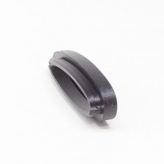
The interface needed some tweaks to fit better, and the flexibility meant that the butt pad did not stay very securely in place. Here’s where the benefit of 3d printing really becomes apparent: I went through 4 revisions in the span of a couple days. I finally settled on a composite part with a hard plastic outer layer and female interface, while the male portion is printed into the same part with the flexible material. The materials are the same color and printed with a mechanical interface such that they can’t be separated since the two polymers do not fuse to each other. There are also some relief cuts to make it easier to remove from the stock.
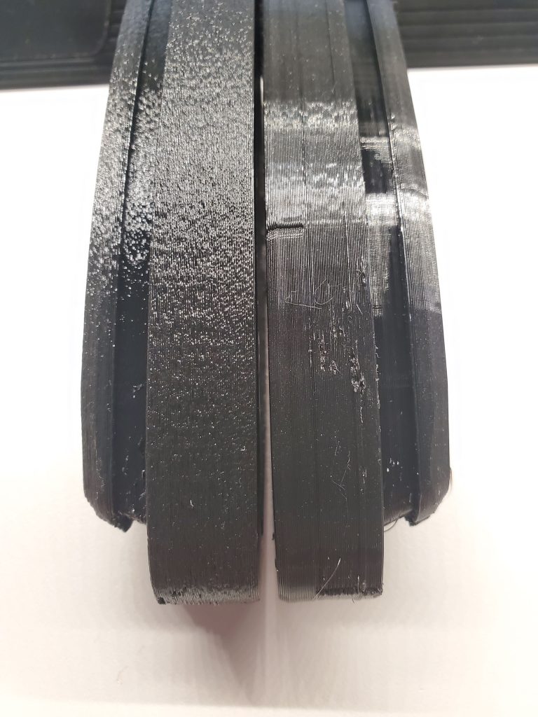
If we look at the model loaded in the slicer, it shows the different materials as well as the “fuzzy skin” option which I’m using to dull the appearrance since both PLA and TPU are naturally glossy. You can see the difference that makes in the comparison image.